Tuning instructions for Dellorto SS carburetors
Detailed technical information regarding Dell’Orto motorcycle carburetors, how to tune, parts diagrams, slide specifications, needle specifications, jet specifications, and atomizer specifications.
Created:
Updated:
This information was gleaned from Moto Italia and the Australian Internet Guzzi Owners Register.
Idle adjustment
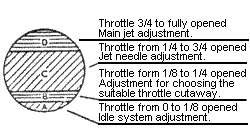
(Throttle valve opening corresponding to the Section A of Figure 1.)
It is necessary first of all to bear in mind that this adjustment must be established always when the engine has reached its normal running temperature.
- In the first idle system, where is subsisting the replacing jet and the air adjusting screw, you must operate on this air screw in order to obtain a correct carburetion, bearing in mind that by tightening it the mixture strength is enriching, while by unscrewing it the mixture strength is weakening.
-
In the second system, where is subsisting the variable screwed pilot jet and the fixed air, the wished engine running will be obtained by operating only on the screw which adjusts the fuel passage; the mixture strength will weaken by tightening this screw and will enrich by unscrewing it.
This second idle system, although it is not exact and sensitive like the first one (suitable to particular uses and engines as told in the general features) allows a better and quicker mixture strength change; it favours therefore easy corrections of carburetion also in the passage runnings and necessary easy enrichments in case of alcohol feed.
With both the idle systems is always advisable to adjust the mixture strength at the slowest runnings, rather about the rich, in order to have then clean passages and pickups without hesitation.
First passage adjustment
(Throttle valve opening corresponding to the Section B of Figure 1).
When obtained a satisfactory idle adjustment, one becomes to the choice of the suitable throttle valve for the intermediate runnings, proceeding as follows.
- If opening gradually the throttle valve for a space corresponding to the part B - fig. 1 the engine running is normal, it means that the throttle valve is suitable.
- If the engine is inclining to fall or it gives backfires for weaken mixture, it means that the fitted throttle valve has a cutaway too high and it is necessary to replace it with another one of lower size.
- If the engine instead is emitting black smoke at the exhaust or it is giving irregular explosions with a heavy running, it means that the fitted throttle valve has a cutaway too low and it is necessary to replace it with another one of upper size.
Jet needle adjustment
(Throttle valve opening corresponding to the Section C of Figure 1).
In order to have the possibility to adjust the jet needle there are on it 5 grooves or holes (the numeration is starting from the top as follows: 1-2-3-4-5). The jet needle checks the carburetion for a throttle valve opening corresponding to the Section C of Figure 1.
If the mixture seems to be weak, the needle must be moved upwards one or two grooves so as to allow a larger flow of fuel at the exit of the needle jet.
If instead the mixture appears to be reach, the opposite must be done, by lowering the needle a few grooves (or holes where existing).
The average position of the jet needle is generally established by us at the third groove (or hole).
Main jet size
(Throttle valve opening corresponding to Section D of Figure 1).
The influence of the main jet is especially felt in the throttle valve opening corresponding to Section D of Figure 1.
It is therefore in this field that it is necessary to operate in order to establish if the main jet fitted is the most suitable one, and precisely:
- If fully opening the gas, the engine begins to turn over with difficulty and instead of increasing in speed,it does not change or even loses and tends to backfire, and if by closing the mixture control piston, a distinct improvement in running is noted, this indicates that the mixture is too weak. In this case the main jet must be replaced by others of the next sizes up until the one, which gives the correct result, is found.
- If the throttle valve is fully turned on, and the engine gives a muffled sound from the exhaust or is missing explosions with emission of black smoke, and by closing the air valve the defect increases, this indicates too rich a mixture. In this case it is necessary to replace the fitted main jet by others of the smaller sizes until the one, which gives the correct result, is found.
A correct carburetion at high speed must be obtained at completely opened air valve.
It must be born in mind that it is advisable to use the size of the main jet which will have given the best result in power or highest speed but that will have however kept the engine at a temperature of safety.
- Exact main jet = normal engine temperature
- Small main jet = higher engine temperature
- Large main jet = lower engine temperature
Only following scrupulously the above instructions and using a sensibility at the highest point when effecting the tests on road and at the brake, one may arrive at a perfect adjustment of the carburetor and therefore at the best performance of the engine itself.
As approximate adjustment data please see at the adjustment key for gasoline.
Base adjustment for gasoline
| Carburetor type | Throttle valve | Jet needle | Needle jet | Main jet | Pilot jet |
|---|---|---|---|---|---|
| SSI-C 18-20-22-23 |
Cat. Nº 1916 70 |
Cat. Nº 2289 R2 at 3 groove |
Cat. Nº 1805 260 |
Cat. Nº 1126 85-95-105-110 |
Cat. Nº 1159 50 |
| SS-A, SSI-A, SSF-A, SSFF-A 24-25 26-27-28 29-30 |
Cat. Nº 2384 90 100 100 |
Cat. Nº 1824 M7 at 3 groove M13 at 3 groove M13 at 3 groove |
Cat. Nº 1805 260 265 270 |
Cat. Nº 1126 115-120 125-130-135 140-145 |
Cat. Nº 1159 50 50 50 |
| SSI-B, SSFI-B 32 |
Cat. Nº 3466 110 |
Cat. Nº 1141 N1 at 3 groove |
Cat. Nº 1121 315 |
Cat. Nº 1126 155 |
|
| SSI-B, SSFI-B 35 |
Cat. Nº 3686 120 |
Cat. Nº 1900 P1 at 3 groove |
Cat. Nº 1121 320 |
Cat. Nº 1126 170 |
|
| SSI-B 36-38 40-42 |
Cat. Nº 4545 130 150 |
Cat. Nº 2470 S1 S1 |
Cat. Nº 1121 325 330 |
Cat. Nº 2475 180-200 220-240 |
Use of alcohol fuel
All our carburetor types of the series SS-A and SS-I are very well suitable also for running with alcohol fuel provided that their general adjustment is revised in the following points.
- Throttle valve: The size generally used for normal super fuels must be replaced by one immediately lower.
- Needle jet: A needle with calibrated hole of higher size must be fitted, bearing in mind that the increase of this hole will be directly proportional to the alcohol quantity contained in the fuel that one is intended to use.
- Jet needle: For fuels with much than the 50% of alcohol end up to the use of methanol, it will be necessary else to replace the needle used for super fuels by one with a thinner end, foreseen by us for this use. The average position advised by us for alcohol fuels is at the 4th groove (or hole).
- Main jet: A main jet oversized from 25 to 50 points about must be fitted according to the carburetor diameter and to the alcohol percentage of the new fuel.
-
Pilot jet: Also for the running in the idle area it will be necessary increase the mixture strength, operating as follows.
-
Idle with rechangeable jet and air adjusting screw:
- for fuels with alcohol up to 50% it will be enough to tighten the air screw, in comparison to the adjustment used for super fuels, just to its complete tightening.
- for fuels with alcohol over the above percentage it will be necessary also to replace the pilot idle jet by a larger one from 5 to 15 points and adjust comparatively the air screw.
-
Idle with variable screw and air fixed:
- with the idle system it is enough to open the screw at pleasure just when a correct idle running is obtained and in the first throttle valve openings.
-
Idle with rechangeable jet and air adjusting screw:
Of course all these instructions are not rigorously fixed but partly entrusted to the judgment and to the sensibility of the experimenter who only by meticulous tests and exactly knowing the features of his engine and of the fuel used, will have the possibility to realize a perfect carburetor adjustment.
As approximate adjustment data please see at the adjustment key for alcohol.
Base adjustment for alcohol (upper the 50%)
| Carburetor type | Throttle valve | Jet needle | Needle jet | Main jet | Pilot jet |
|---|---|---|---|---|---|
| SSI-C 18-20-22-23 |
Cat. Nº 1916 60 |
Cat. Nº 2289 R4 at 4 groove |
Cat. Nº 1805 275 |
Cat. Nº 1126 130-135-140-145 |
Cat. Nº 1159 60 |
| SS-A, SSI-A, SSF-A, SSFF-A 24-25 26-27-28 29-30 |
Cat. Nº 2384 70 80 90 |
Cat. Nº 1824 M3 M3 M3 |
Cat. Nº 1805 280 280 280 |
Cat. Nº 1126 150-155 160-170-180 190-200 |
Cat. Nº 1159 70 70 70 |
| SSI-B, SSFI-B 32 |
Cat. Nº 3466 80 |
Cat. Nº 4338 N2 |
Cat. Nº 1121 350 |
Cat. Nº 1126 220 |
|
| SSI-B, SSFI-B 35 |
Cat. Nº 3686 90 |
Cat. Nº 4339 P2 |
Cat. Nº 1121 360 |
Cat. Nº 1126 250 |
|
| SSI-B 36-38 40-42 |
Cat. Nº 4545 100 110 |
Cat. Nº 2470 S8 S8 |
Cat. Nº 1121 370 380 |
Cat. Nº 2475 250-280 310-340 |
Figure 1 - Proving diagram of the different running phases.

Photo courtesy of Australian Internet Guzzi Owners Register.
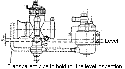
Figure 2 - Proving diagram of the exact level position.

Photo courtesy of Australian Internet Guzzi Owners Register.
Table A - for the choice of carburetor diameter
| Cylinder displacement | Choke adaptor diameter for the undermentioned motorcycle classes | ||
|---|---|---|---|
| Sport | Supersport | Racing | |
| 125 cc 4 st. | 20 | 22 | 28 |
| 125 cc 2 st. | 22 | 24 | 30 |
| 175 cc 4 st. | 24 | 26 | 30 |
| 175 cc 2 st. | 26 | 28 | 32 |
| 250 cc 1 st. | 26 | 28 | 32 |
| 250 cc 2 st. | 28 | 30 | 35 |
| 350 cc 4 st. | 28 | 30 | 35 |
| 500 cc 4 st. | 30 | 32 | 38 |
| 600 cc 4 st. | 32 | 35 | 40 |
| 750 cc 4 st. | 35 | 38 | 42 |
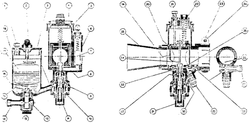
Proving section of SS-A carburetor with idle system of rechangeable jet and normal float chamber.

Photo courtesy of Australian Internet Guzzi Owners Register.
- Fixing float chamber top screw
- Tickler
- Float chamber cap
- Mixing chamber top
- Mixing chamber cap
- Carburetor body
- Air valve
- Air valve channel
- Jet holder
- Holding bolt for float chamber
- Main jet
- Filter
- Banjo nut
- Banjo
- Needle seating
- Float needle
- Float
- Float chamber body
- Throttle valve
- Choke adapter
- Throttle stop screw
- Throttle cable adjuster
- Outlet clip
- Outlet cable clip
- Idle second hole
- Idle air channel
- Air adjusting screw
- Idle first hole
- Pilot jet
- Idle fuel channel
- Jet plug
- Needle jet
- Spray tube
- Jet needle
- Air tube
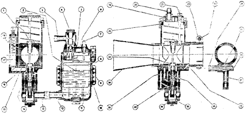
Proving section of SSI-B carburetor with idle system of rechangeable jet and remote float chamber SS-I.

Photo courtesy of Australian Internet Guzzi Owners Register.
- Jet needle
- Float
- Banjo
- Banjo nut
- Jet needle seating
- Jet needle
- Tickler
- Rocking lever
- Clamp ring for float chamber
- Clamp ring gasket for float chamber
- Float chamber body
- Petrol outlet connection
- Banjo
- Carburetor body
- Choke adaptor
- Air valve channel
- Air valve
- Throttle valve
- Mixing chamber top
- Throttle cable adjuster
- Throttle stop screw
- Outlet clip
- Outlet clip pin
- Pilot adjuster
- Pilot needle insert
- Idle air channel
- Idle fuel channel
- Idle outlet channel
- Needle jet
- Main jet
- Banjo nut
- Jet holder
- Air channel for emulsioning
- Air tube
- Spray tube
- Mixing chamber cap