Update 8 - December 2010
Time flies when I look back, the V6 project has progressed, but it's never as much as you would like. There are many competing interests, like my lovely son Aris who came home with the idea to start 50cc racing. Of course I supported him in his idea and so we bought a moped and made it racy and fast. Next season I will spend 2 Saturdays from March to October which is exactly the season the Laverda Museum visitors are coming along. The Museum has had a lot of visitors, mostly Laverda people from all over the world who are just in Amsterdam a couple of days and …………please……. really want to make a visit. Then there is my garden which needs plenty of attention because my lovely wife is unfortunately not able to do it. But it is all fun and I will not complain about it as I still have time to work on the V6 projects. Some days 2 hour, some days 8 hours.
One of the decisions I have taken is to use the engine of the 2007 purchased V6 (built in 1991) for my 2nd V6 project, the completely recovering of the prototype. This engine is the original prototype engine with carburettors of 30 mm and has some small differences compared to the 24-hour version that had 34 mm carburettors. The engine that I am producing now with all the parts has the latest version of the crankcases and I also do have the latest 34 mm heads.
The envisaged prototype, as shown on the Milan show of 1977, will then have the original engine and the V6 built in 1991 will also receive his 34 mm engine with original crankcases, heads etc. so finally it will all come on the right spot.
What has happened in the last months?
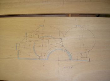
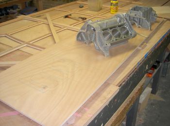
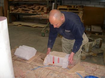
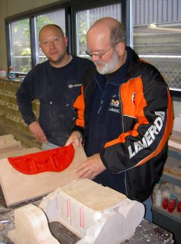
As I plan to have both V6’s ridden in future I prefer to cover myself against some serious and inevitable crankcase damages and so I called a friend who is a mould maker and asked him to make new moulds for the crankcases. We do have the possibilities now and later, if both projects are ever finished, the work will be much more complicated.
The oil pump parts are finished now and so are almost the camshaft supports.
The cranks ordered in September 2009 arrived in May this year, and after a complete check several failures were found and after a some serious discussions they offered to make 2 complete new ones. So no hard feelings from my side. After another 1000 apologies, 3 months later they arrived and they are and look very good now.
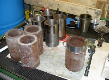
Concerning the engine, progress has been made as well. 10 Years ago I already purchased the material that was necessary to produce the liners. Now they have been made and put into the crankcases, bored and are now ready for the honing process.
Another aspect was the head seal/gasket - this job is done by a red copper ring in a V grove.
When fitting the head the copper distorts and will seal……. I hope. In 1978 they were made from 1mm copper wire, soldered and afterwards by hand machined. I did not like this method and made some special cutting tools and have machined them on the CNC lathe from billet copper material. A precise and nice experience.
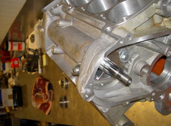
The shaft that runs parallel to the crankshaft, mainly for the chain drive to the heads and for the transmission to the rev counter, has been produced as well as the rev counter shaft with the well known inside square.
As I have chosen to use another camchain size, as the original one cannot be supplied anymore in a high precision chain, I had to renew all sprockets and that caused some serious calculations. Hopefully no mistakes are made as this has cost me quit a lot of time to draw, to turn, to mill, to bore, to make splines, to harden and to grind. Future will tell me more!!
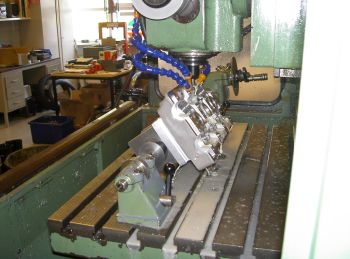
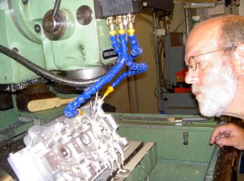
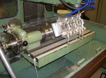
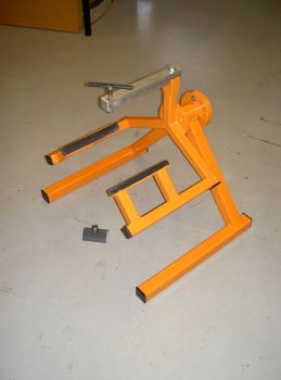
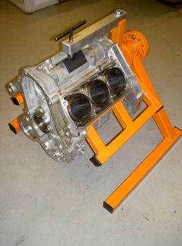
To build up the engine I have made a nice orange jig that can rotate the engine.
Last week I have been at Uwe Witt in Germany who will make a new ignition for the V6’s and I have taken back the original unit. For my 2nd V6 project I need to make a completely new casting mould for a new distributor housing and an injection mould for a new rotor as both parts only where used especially for the Laverda V6 and were never used in the automotive industry. Next month I will make a start with this work and I expect it will be a troublesome job.
Having read this back again it is not too bad what I have done last months. It’s all a puzzle
and in this case a real big one.
Will be continued……………..
Many regards,
Cor
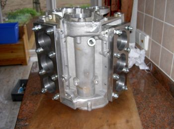
To be covered against damages new moulds from the crank casings will be made by my friend who is a mould maker. Believe me this is a hell of a job.
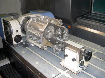
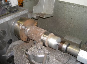
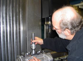
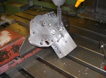
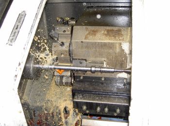
One of the very last operations at the crank cases. The diameters for the liners will get there final sizes.
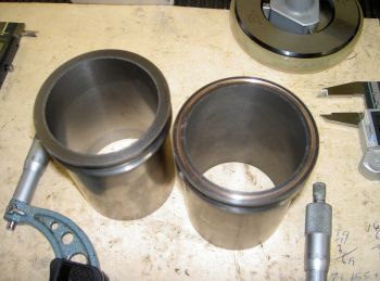
This piece of rusty material has been machined into a nice cylinder liner.
.
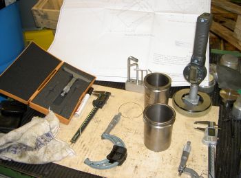
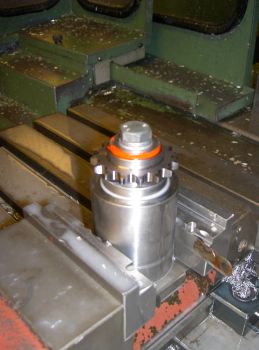
The final operations on the liner. Clearly can be seen the V grove on top of the liner and
one of them the copper ring can be seen.
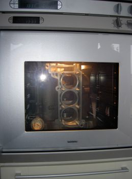
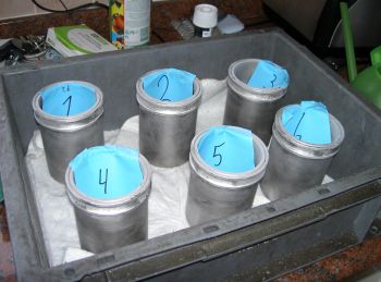
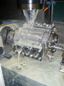
The engine was heated up to 95 degrees and the liners were cooled down to -18 degrees.
Then you have about 2 minutes to push them all in the upper crankcase.
Liners assembled.
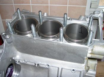
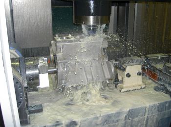
With a still very hot engine the liners are pressed to their seats with help of some special made ground plates.
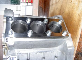
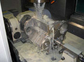
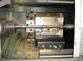
With the plates still in their position the liners are bored to the size for honing.
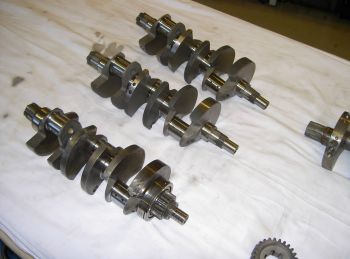
Four cranks on a row.
The 2 upper crankshafts are the new made ones, the lower is the one that came out of the prototype engine. Very far right just a tip of the fourth that was acquired with the parts in 1999. Also this crank has cracks and will not be used.
One of the last jobs on the oil pumps.
Making a free runway in the supports for the camshafts. Also these parts are nearly finished now.
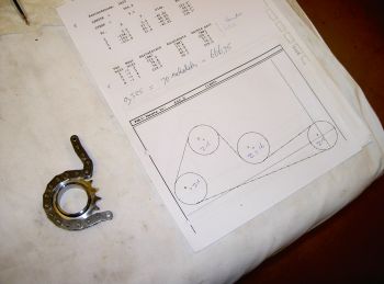
To make the new sprockets several calculations and drawings had to be made on the AutoCad system. From there the program was made for the milling machine.
But first, with help of a skilled “chain-man” the length was checked and compared to the old chain that was used. Also the diameters and number of teeth were calculated.
3 Different types of sprockets had to be made. To mill the teeth I had to make a small jig to fix the sprockets properly and centrically (sorry, not a clear picture).
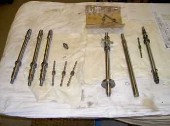
New parallel shafts were made plus the shafts for the rev counter drive because the ratio of the prototype engine was not good for my rev counter and I anyway had to make a set of shafts for the other engine.
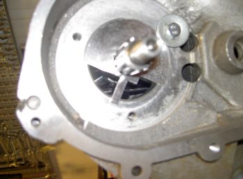
I made 2 aluminium dummy bearings and milled parts away to have a check through the hole
for the tolerance between the gears. ( sorry not sharp again ) After this the shafts were hardened and ground.
To assemble the engine in a later stadium a special rotating stand has been made.
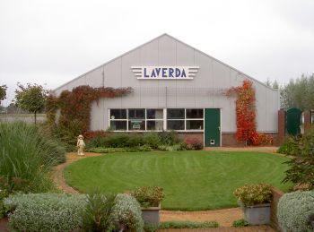
This is how the Laverda Museum looked in September 2010-11-09.