Update 11 - May 2012.
Dear readers,
Our cold and very wet winter absolutely did not upset the V6 project. I could spend a lot of time in my workshop - how lucky a man can be with a wet climate like ours!!
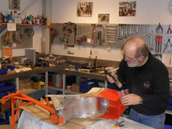
In early December I got a message from the Belgian welder Jef in which he told me the prototype rear frame/ oil tank has been finished as well. He arrived with his wife when he brought the frame to our home and we had a splendid evening together. This man deserves a medal.
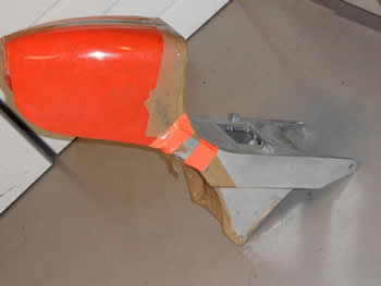
Both fibreglass tail sections have been fixed to the aluminium rear frame and are ready now to be painted. Next time all of the painted pieces will go to the paint shop where they will prepared for the finishing paint. I prefer to first build up both bikes in an unpainted state and after comprehensive testing of the engines I will disassemble again and finish into the final colour scheme. Orange of course!
After much research and waiting I got a phone call in December to advise that the plastic material for the distributor rotor - the granulate - had arrived and fortunately in the exact right composition that the man of Magneti Marelli had advised me.
in January I went to the company with my heart beating, together with the mould and pieces that I had made. 2 Hours later I was outside again with a big smile on my face. The result is perfect.
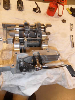
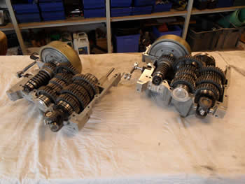
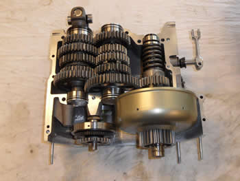
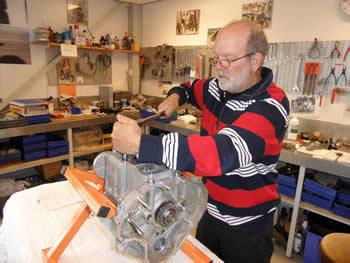
At the same time I had been starting to assemble both gearboxes. The shifting mechanism, the gears, shifting drum and the shaft, they all had to be assembled with shims. Lots of hours were spent with grinding the shims and assembling and testing. Both gear boxes are finished now. Only a little change will have to be made on the upper part and after that both halves can be finally paired again.
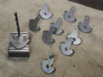
For the carburettors I was searching for years for the right Dell’Orto levers for the 2nd V6. They were unobtainable and finally I decided to spend my time making them instead of searching for them. I made them from steel plate, bend and welded them. They are finished too and only need to be galvanised. I have enough of them for another 3 V6’s.
For the cylinder head I made new water collectors. The original ones looked really terrible. Now they are fine.
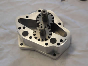
When I started assembling the oil pumps I found out the gears had become a bit bigger through the hardening process. Because of this the gears had no play in the pump housing. For these gears a different kind of material was used than the material the gears of the gearbox were made of. After having had a consultation with a good friend it was decided to try to get the teeth a little smaller with valve grinding paste. After having made a jig that was fitted on the lathe, the teeth of the gears became some hundreds of a mm smaller after 2 hours of “lapping” and their size was now good to fit into the oil pumps. After 2 days all gears were at the right size again. Any way I was glad it wasn’t necessary to remake them.
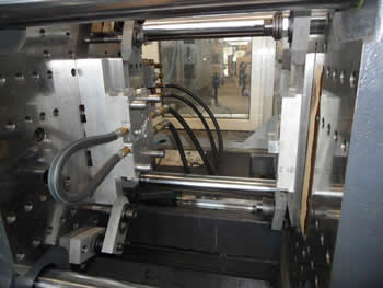
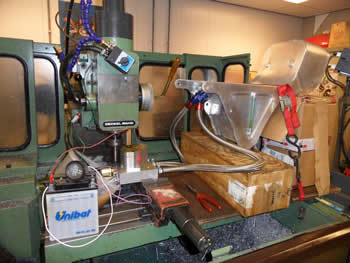
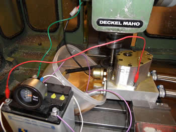
To test the oil pumps a manifold was made that had the same mountings and oil holes as the V6 crankcase. In the manifold the pressure valve, the pressure sensor, a tappet for the oil flow and all connections to the oil tank were made. On the milling machine I now could approach the reality. All 3 pumps worked fine and at 1500 rpm ( actually 3000 crank revs ) they delivered 4 bar oil pressure. Later on I have to check the pressure at higher revs in the engine but for now this is good enough to work with when the engine will be started.
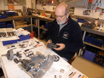
A start has been made in assembling the first engine. The crankshaft and con rods have been checked on their play with help of ”plastigauge” and they were all perfect. So this is a good beginning and the engine starts getting it's original shape again.
But now my son Aris has started racing again and also the Laverda museum runs at full speed. Last month I had an extreme number of over 500 visitors! Especially by 2 events that were held. So in coming months less time can be spent in the workshop…. unfortunately.
Anyway, both V6’s have made great progress in the last few months.
The only problem is still the electronics of the ignition. Last months nothing or almost nothing has happened in Germany and so I hope things will change in a positive way now because what is a V6 without ignition?
Enjoy reading and until next time.
Many regards,
Cor
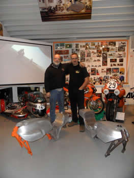
Welder Jef with both rear frames / oil tanks
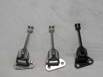
2 Extra clutch levers and bearing housings were made.
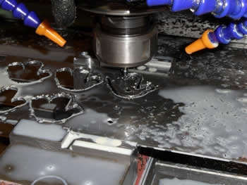
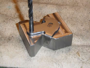
The little bending jig for the levers.
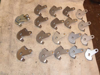
More than enough for a couple of V6's.
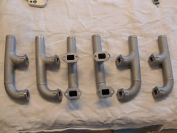
Manifolds for the hot water outlet from the heads.
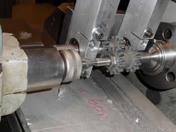
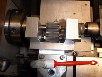
“lapping” the oil pump gears with lapping paste.
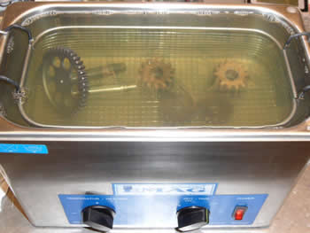
After that ultrasonic cleaning the gears.
Now the gears will fit perfectly in the pump housings.
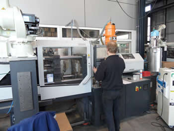
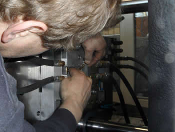
By hand the brass rotor tips were put in the injection mould. After a push on the start button the mould closes and the heated granulate will be injected under high pressure. After a little time the mould will open and the complete rotor can be taken out of the mould.
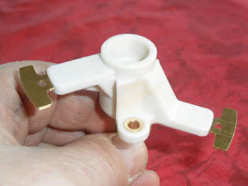
And here he is!
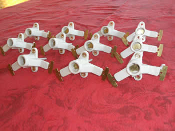
11 Good rotors in total. I will never need them all.
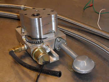
Manifold for testing the oil pumps.
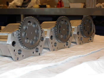
3 Good oil pumps. 2 Ready for building in and 1 as a spare part.
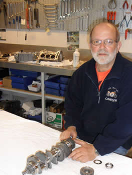
Assembling the engine can be started now. On this picture assembling the gears on the crank shaft.
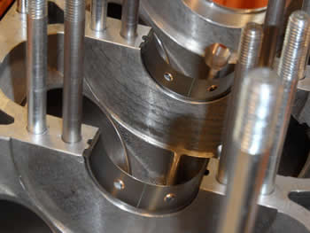
With help of “plasigauge” the clearance of the crank and connecting rods in the bearing shells can be measured. All clearances were perfect.