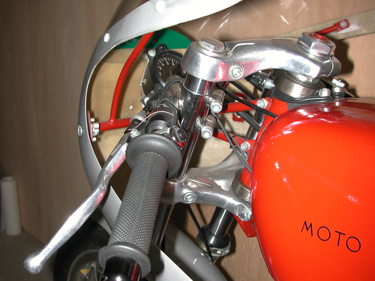
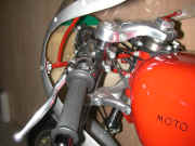
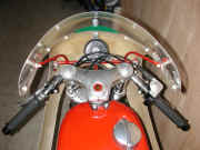
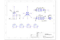
Steering Head Assembly
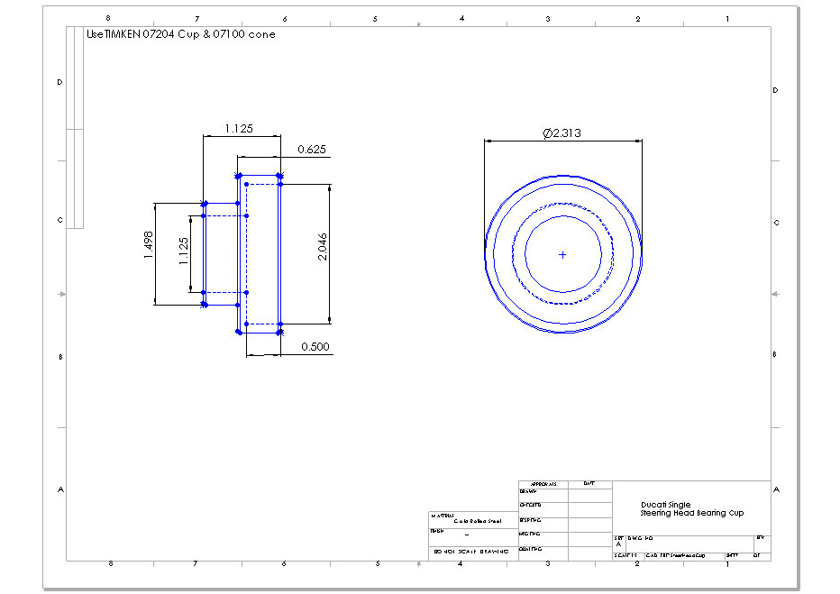
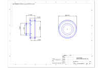
Machine new replacement cups to accept Timken tapered roller bearings 07204 & 07100. Cut the top of the frame's head tube down to 134.5mm OAL and bore to accept new bearing cup.
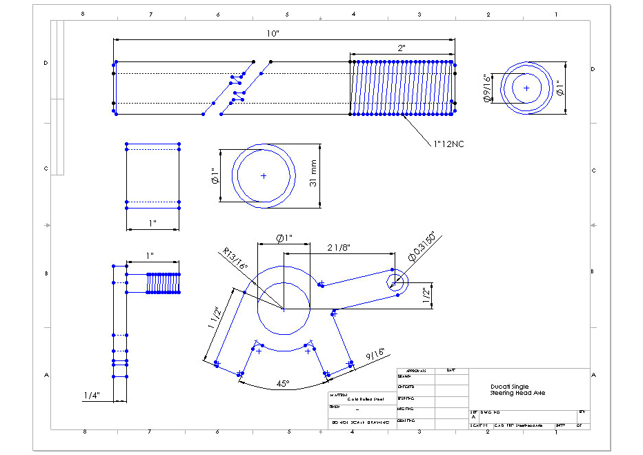
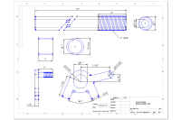
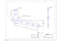
Use one inch diameter cold rolled steel bar drilled through 9/16" for the steering axle. The length of the OAL steer axle is determined by the length of the frame's steer tube and yoke thickness. Machine a 1" X 12 thread for the crown nut. Turn a bushing to fit the lower clamp 1" ID X 31mm OD by 1" long. Heat the bushing and press onto the steer axle. Fabricate the steer stop plate and weld to the bottom of the steer axle (see drawings).
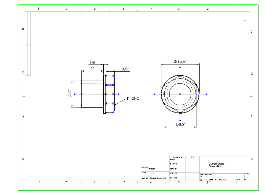
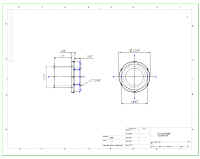
Machine an aluminum crown nut with 1" x 12 ID thread and 31mm OD to fit the top clamp (see drawings). Use a 1" X 12 lock nut and 1" thrust washer from your bearing supplier.

|
|
|
|
1280x960 image
|
1280x960 image
|
1280x960 image
|
|
|
|
|
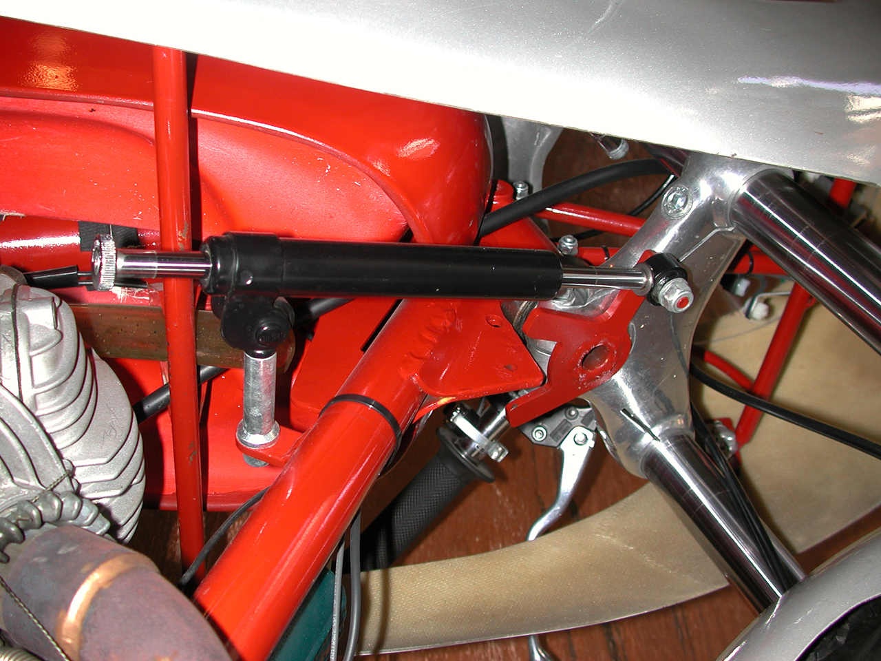
Steer Axle & Stop
|
Tapered Bearing Cups
|
Crown Nut
|
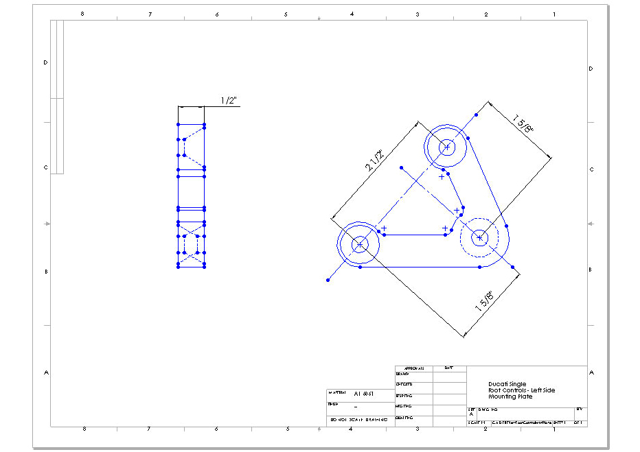
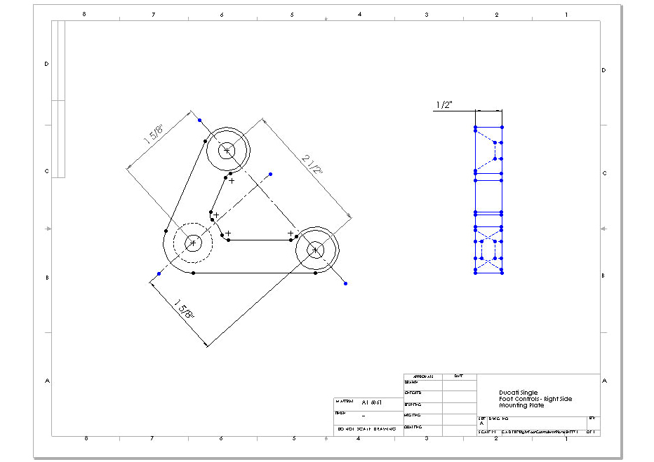
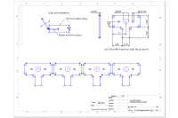
Foot Controls
Weld a second threaded bushing on the frame below the existing one designed for rear foot pegs. Drill and tap both bosses to M10 and use flat head screws.
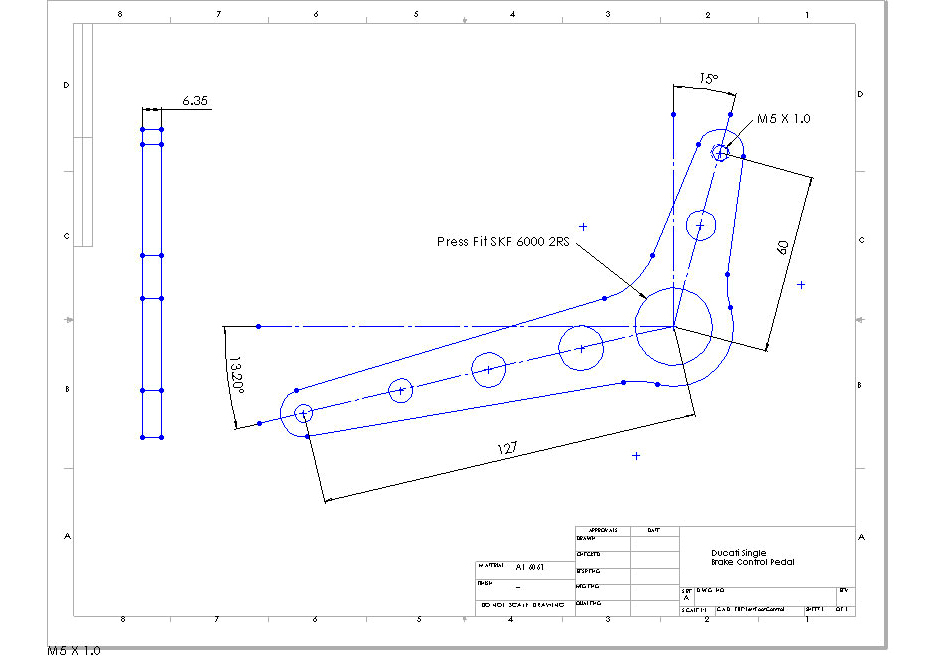
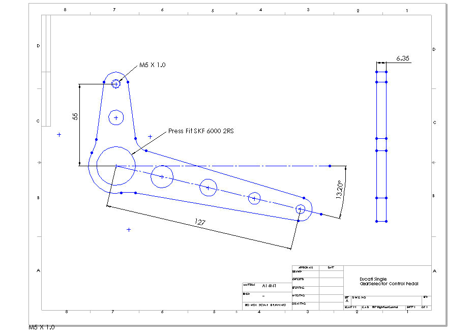
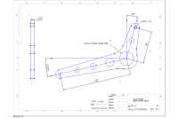
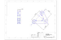
The hangers are cut from ½" aluminum plate with a wire EDM machine (see drawings). Take the iges format drawing files to any machine shop with a wire EDM. Drill and counter sink the mounting holes.
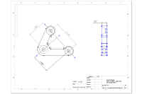
Fabrication note: Print the drawings at full scale and use as a template to fabricate the foot controls from ¼" aluminum plate. Use spray adhesive from an art supply store to fix the paper template onto the aluminum plate. Center punch the hole centers and cut the profile using a band saw. Use a belt sander and drum sander mounted in a drill press to finish the edges. Drill, tap and bore the holes.
|
|
|
1280x960 image
|
1280x960 image
|
|
|
|
Left Foot Control
|
Right Foot Control
|
|
|
|
Left Mount Bracket
|
Right Mount Bracket
|
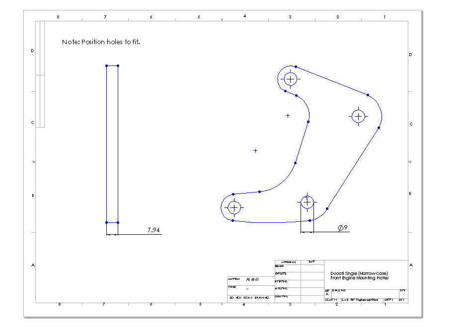
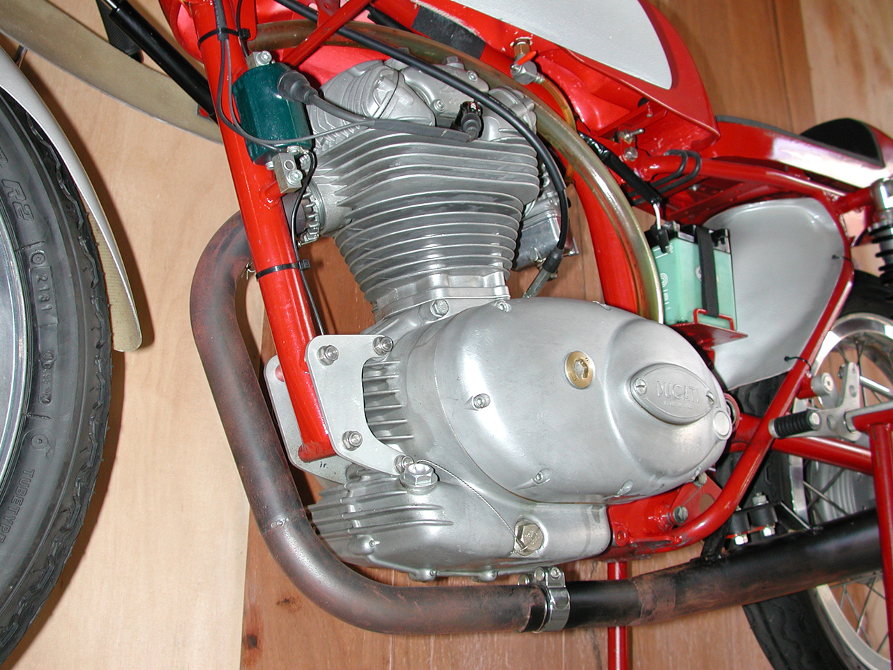
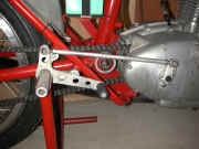
Engine Mounts
The rear engine mounting holes should be drilled and then reamed to .375 in. to prevent the engine from "working" in the frame. Assemble the right and left cases, located on the dowels, and secure them together with several M6 cap screws. A milling machine should be used to drill square through the cases and the dowel that is located in the bottom hole. Use 3/8" stainless steel bolts, washers, and nylon lock nuts. The rear bolts are 3 1/2 inches long.
Place the disassembled engine cases in the frame and locate the front mounting holes. Fabricate the front mounting plates to suit. Use M8 stainless bolts, washers, and nylon locking nuts. The front bolts are 90 mm long.
Fabrication note: Print the drawings at full scale and use as a template to fabricate the foot controls from aluminum plate. Use spray adhesive from an art supply store to fix the paper template onto the aluminum plate. Center punch the hole centers and cut the profile using a band saw. Use a belt sander and drum sander mounted in a drill press to finish the edges. Drill, tap and bore the holes.
|

|
|
Front Engine Mounting Plate
|
1280x960 image
|
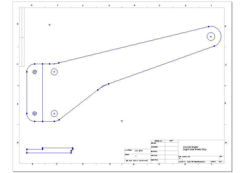
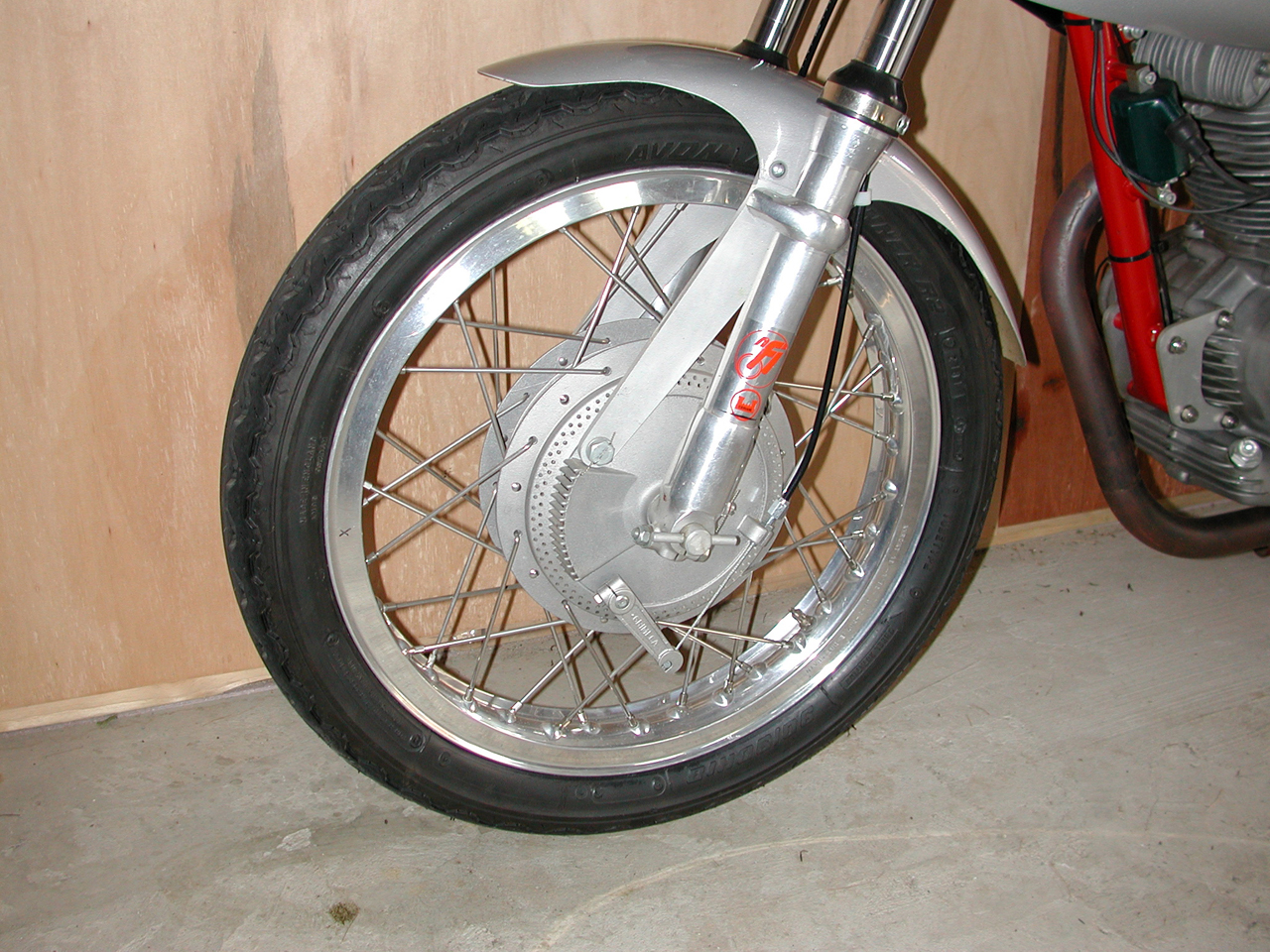
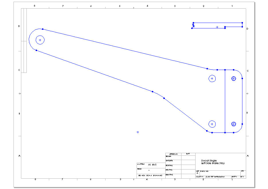
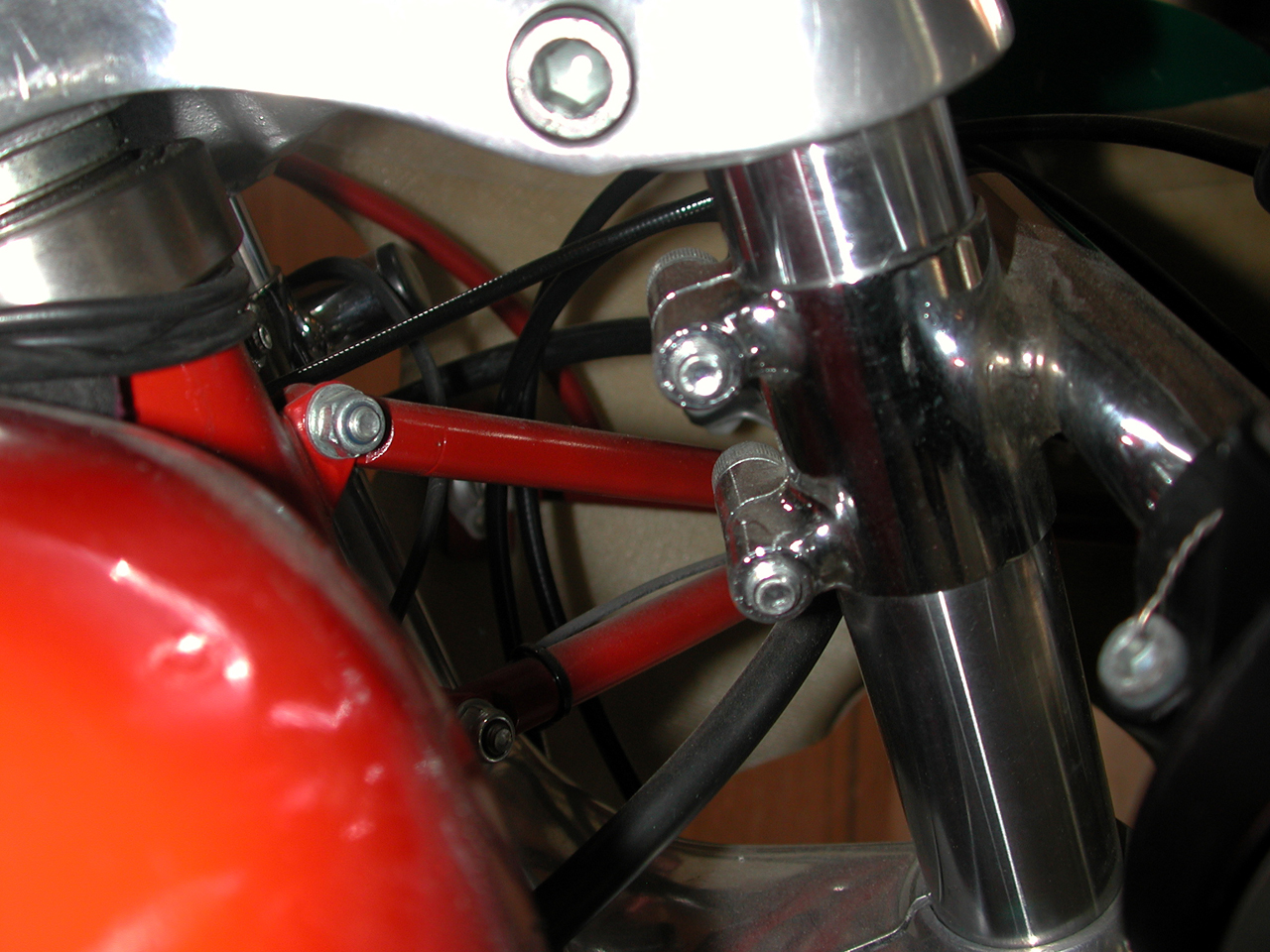
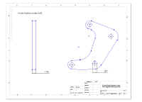
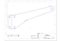
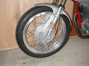
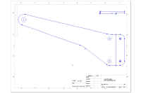
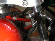
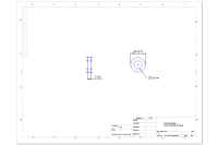
Front Brake Stay
The following drawings are designed to fit the Ceriani forks and Grimeca double sided brake.
Fabrication note: Print the drawings at full scale and use as a template to fabricate the foot controls from aluminum plate. Use spray adhesive from an art supply store to fix the paper template onto the aluminum plate. Center punch the hole centers and cut the profile using a band saw. Use a belt sander and drum sander mounted in a drill press to finish the edges. Drill, tap and bore the holes.
|
|
|
|
Right Brake Stay
|
1280x960 image
|
Left Brake Stay
|
|
|
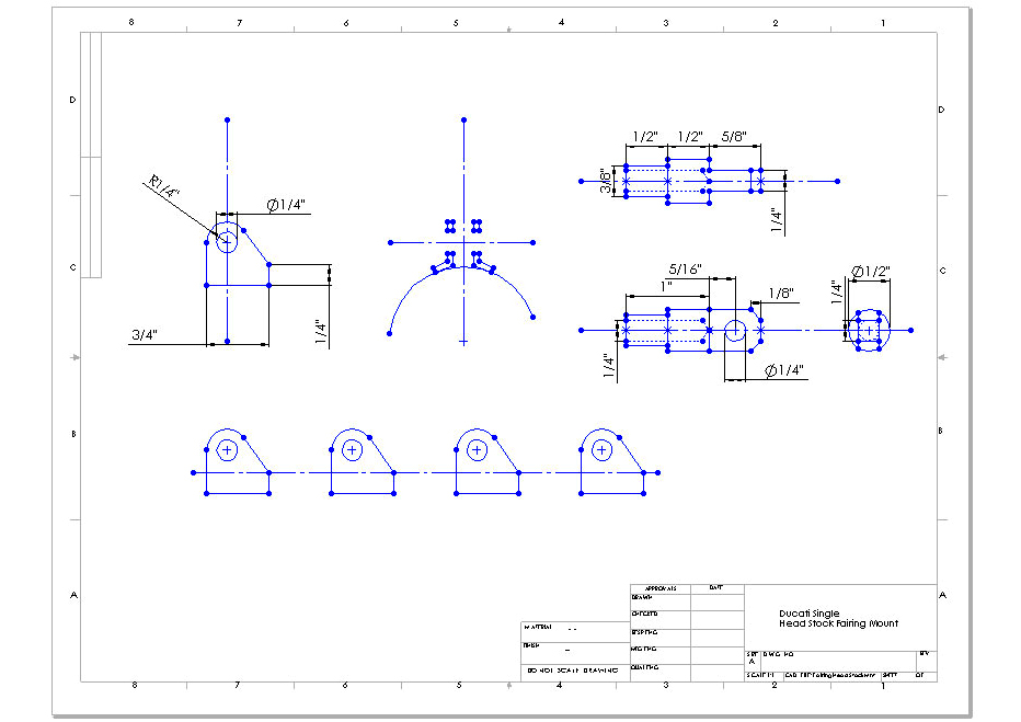
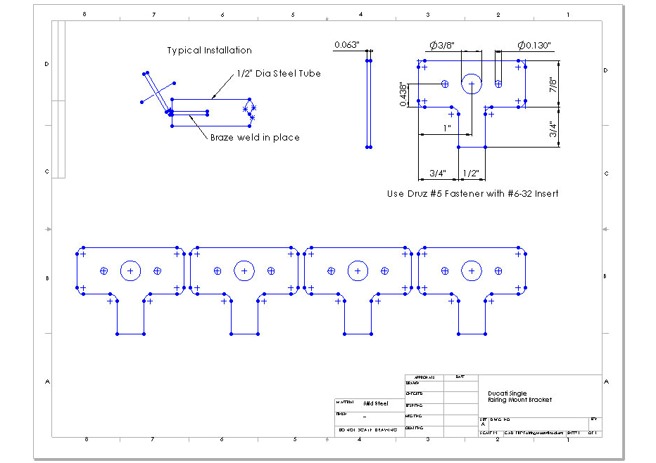
Fairing Mounts
The mounts in the following drawing are designed to work with 1/2" steel tubing.
|
|
|
1280x960 image
|
1280x960 image
|
|
|
|
Headstock Mount
|
Druz Fastener Mounts
|
Swing Arm
Buy new bronze bushings, pivot pin and shims. Press in the new bushings so that the are flush with the outside face of the swing arm. Take the swing arm to automotive machine shop that does suspension work. Have them line hone the bushings on the machine they use to replace king pins in the control arms for cars.
When you install the swing arm measure use feeler gauges to measuring the clearance between the frame and bushing. Install the correct thickness shims on the pivot shaft.
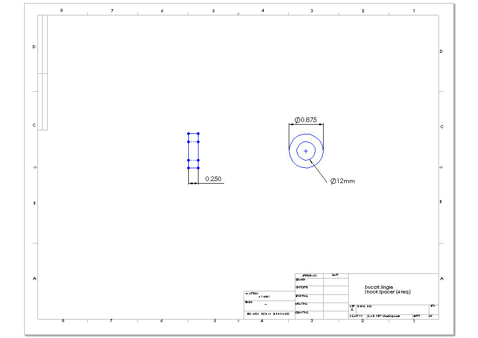
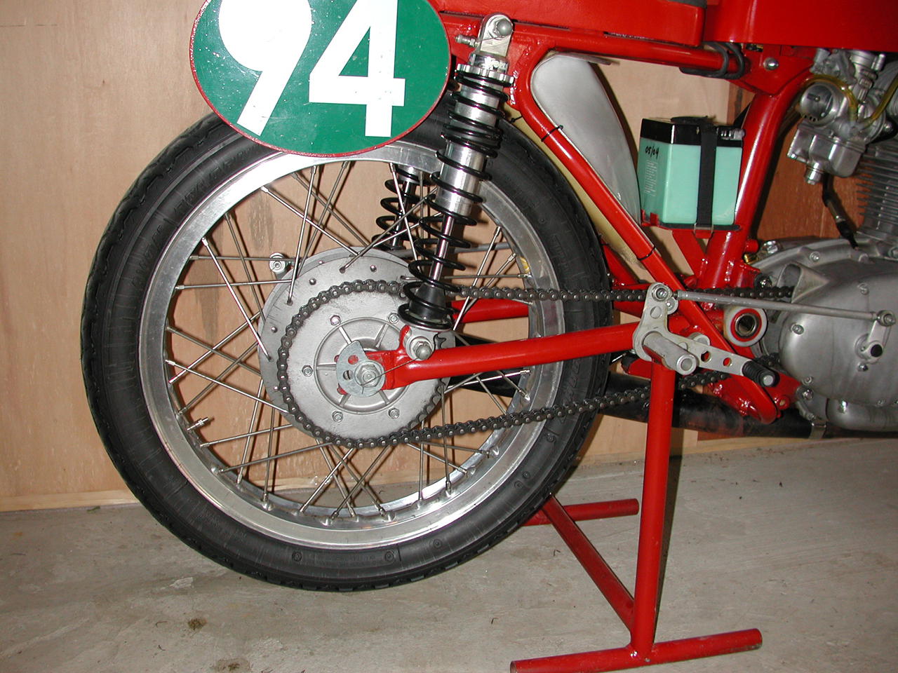
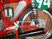
Rear Shocks
Use Works Performance replacement shocks:
- 13 inch Shocks with 3 1/2 inches of travel
- 10mm mount bolts & 7/8" eyelets
- Dual Rate Spring (Order by rider weight and ability)
- Steel or Aluminum Body
- Shock mount spacers: ¼" thick by 7/8" diameter with 12mm diameter hole.
|
|
|
Top Shock Mount Spacer
|
1280x960 image
|
|